Core cutter method is a type of field density test performed to evaluate the in-situ density of cohesive or clayey soils. It is a very easy and simple test that includes driving of a steel core-cutter with sharp blades into the fill. So, this method is not suitable for coarser soils as the core may not penetrate easily.
Like other methods described here, core cutter method of field density test is used to determine the in-situ density and compaction of soil embankment or subgrade.
Why Core Cutter method is used in Civil Engineer?
In order to evaluate the compaction of soil we have achieved at site; we have to compare it with MDD.
MDD – is maximum dry density. It is determined in the laboratory by either of the following methods;
- Standard proctor test also known as AASHTO Compaction test
- Modified Proctor Test
I’ve explained these methods in detail in my previous post.

Maximum dry density is the maximum value of compaction that can be achieved from fixed compaction effort and type of soil.
It has a slight edge on other methods of field compaction. It is a rapid method that require less time for execution and also the calculations are very easy and straight forward. There is minimum chance of error while calculation.
I’ve explained in detail step by step calculation involved in different field density test methods including the core cutter method. Read this post in addition to the calculation guide to learn maximum. Field Density Test Calculation
What does it mean by 95% compaction?
You can find the required value (%age) of compaction in your project’s specification. In most general uses it is taken as 95%. This means that if field compaction is 95% of the laboratory density only then the soil layer can be declared as fully compacted.
Otherwise you’ve to compact the layer more by two or three more passes of the roller compactor.
Why 95% and not 90% or 80%?
We do FDT test on soil so as to avoid post construction settlement in a structure. The foundation engineer – if you’re not the one, know that any settlement beyond 1 inch could be destructive for serviceability and sustainability of the structure.
Whether you’re constructing a dam, house, building, plaza or even a highway; only a well-compacted soil underneath the structure can sustain superimposed loads.
Proctors – a soil expert from California, along with his friends found that a compaction of above 95% gave 95% confidence rate that the post construction settlement would be less than one inch of the soil.
Background of Core Cutter Method
As you know from the definition of density – it is weight per unit volume.
So we’re in need to know how much weight of soil embankment is present in a hole of known volume.
We can correlate that a well compacted soil would have comparatively more weight of soil solids in a fixed volume of embankment than the poorly compacted soil.
In Core Cutter Method of Field Density Test, a seamless steel tube is hammered and pressed into the soil layer. The volume of the tube is known ahead. The mass of the soil pressed inside the tube is determined. This mass is divided by the known volume to get the density.
Suitability of the test
In flexible asphaltic pavements, you’ve various gradation of aggregates in subgrade, sub-base and base courses. Similarly, underneath the building foundations or floors you’ve got diverse natured soils.
You can’t actually use core cutter in all cases.
Can you imagine how hard it would be to hammer the steel tube in a layer of soil containing boulder and gravels?
You can’t do that; so this core cutter method is only suitable for cohesive soils with fine size of aggregates.
The test method has been standardized by Indian Standard IS : 2720. You can download the standard from this link.
According to IS Standard, this test method is only suitable for fine-grained natural or compacted soils free from aggregates. The 90% or more particles of the soil should pass sieve of 4.75 mm aperture size.
Apparatus
Before moving on to the standard procedure let’s have a look at the apparatus first;
- Steel Rammer – this is a 9 kg weight hammer with a staff to hold on to it.
- Cylinder Core cutter – it is a sharp edged seamless steel tube with 100 mm internal diameter and length of 130 mm.
- On the top of the cylinder a Steel dolly is fitted. It has an internal diameter of 14 cm and height of 7.5 cm.
- Sharp blade edge for trimming the soil sample
- Containers for water content determination
- Steel Ruler
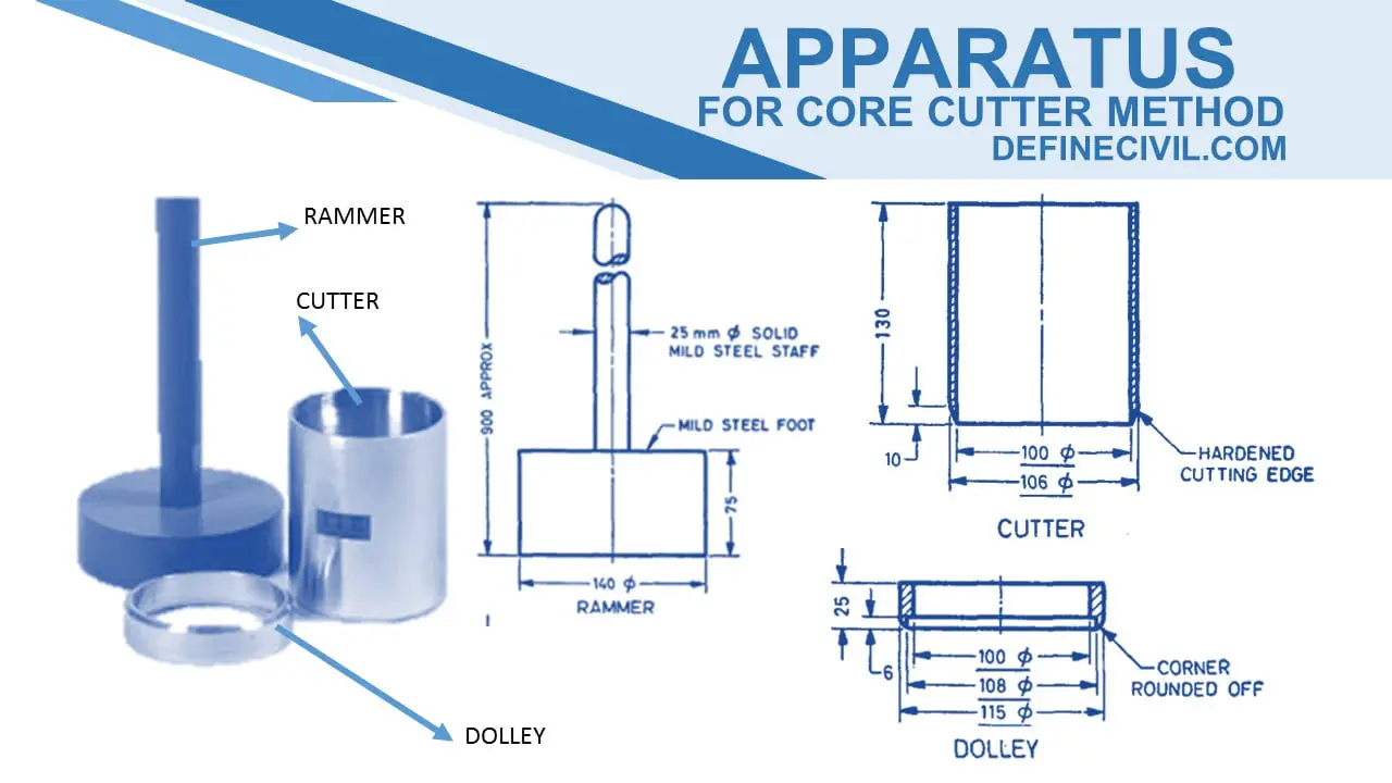
Core Cutter Method Apparatus
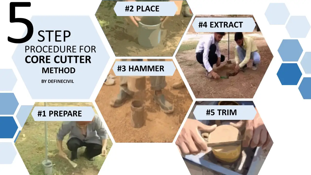
Procedure
- First we measure the internal diameter (Di) and height (H) of the core so that the volume (V) of the steel tube can be determined in the laboratory.
- We also take note of the weight (Wc) of the core by using physical balance.
- We then take the apparatus to the site and the soil, to be tested, was levelled and cleaned.
- Then we fix the dolly on the core and start pressing the core in the soil. The ramming was done till only 15 mm of the dolly remains above the soil.
- After that we remove the soil surrounding the core so that it can be pulled off easily.
- Then we remove the dolly from the apparatus and the protruding soil sample was flushed by using a straight edge blade.
- We take note of the weight of the soil including the core (Ws+c)
- After that we take representative sample for moisture determination of soil.
Observation & Calculation
here is a step by step calculation;
- Internal Diameter of the Core = Dc = 10 cm
- Height of the Core = Hc = 15 cm
- Volume of the Core = Vc = 1178.25 cm3
- Weight of the empty core (Wc ) =1.7 kg
- Weight of the Soil sample + Core = Ws+c = 3.3 kg
- Weight of the soil sampel = Ws = Ws+c – Wc = 1.6 kg
- Bulk density of the soil = ϒb = Ws / Vc = 1600 / 1178.25 = 1.357 g / cc
- Moisture content = m = 10 %
- Dry density of soil = ϒd = ϒb / (1+m) = 1.357 / (1+0.1) = 1.233 g /cc
| FIELD DENSITY TEST OF SOIL BY CORE CUTTER METHOD | Logo1 | Logo2 | Logo3 | |||||
| Test Fill at Some Location A | ||||||||
| Type of Soil | Type of Material A | Test Date | 31-May-15 | |||||
| Layer | X layer | Group No. | Location Jalala | |||||
| TRIAL NO. 1 | 1 | 2 | 3 | 4 | 5 | |||
| Diameter of the Core Dc | m3 | |||||||
| Height of the Core Hc | kg | |||||||
| Volume of the Core Vc | Nos. | |||||||
| Weight of the Empty Core Wc | Nos. | |||||||
| Weight of the Soil + Core (Wc+s) | cm | |||||||
| Weight of the Soil Sample | kg | |||||||
| Bulk Density of the Soil Sample = ϒb | kg | |||||||
| MOISTURE CONTENT | Weight of Tin | gm | ||||||
| weight of tin + wet soil | gm | |||||||
| weight of tin + dry soil | gm | |||||||
| weight of water content | gm | |||||||
| moisture contet | % | |||||||
| Results | Dry Density | kg/m3 | ||||||
| Relative Compaction | % | |||||||
Wait! Its Not yet Over
Yes Dear, Its not yet over. Because I have made a ready to use excel sheet for you to just put in values of field density test by core cutter method and it will automatically calculate the bulk density, moisture content and dry density. You can also calculate the relative compaction.
You can download this excel file for core cutter method by clicking the button below.
Download the Excel Spread sheet