Plate Bearing Test also known as plate load test or static loading test, is an in-situ load bearing test of soil. The activity of plate bearing test is performed in order to determine the bearing capacity of soil underneath that is likely to take the anticipated load of temporary or a permanent structure.
It is important to note that this test method assumes that soil strata down towards the depth and in relation to the influence of stresses are reasonably uniform.
Purpose of Plate Bearing Test
The purpose of plate bearing test is:
- Confirmation of the assumed bearing capacity during design stages
- Estimate the design parameters related to soil bearing capacity
- Estimate the likely settlement of the foundation under the working load.
The applications and utilization of the results achieved after performing the plate bearing test are great many. This test is performed in road, highway projects or for the shallow foundations in cases of buildings and infrastructures.
It can also be used for the design of temporary working structures such as working platforms for piling rigs or pads for crane outriggers.
Plate Bearing Test is conducted for Ground Bearing Pressure testing in support of Temporary Works, Piling Mats as well as Crane Foundation.

Plate Bearing Test Code
The American Society for Testing Materials (ASTM) has standardized this test procedure in two codes one is ASTM D1194 and ASTM D1195. ASTM D1194 stating “Standard Test Method for Bearing Capacity of Soil for Static Load and Spread Footings” has been withdrawn by ASTM in 2003.
The other one ASTM D1195 stating “Standard Test Method for Repetitive Static Plate Load Tests of Soils and Flexible Pavement Components, for Use in Evaluation and Design of Airport and Highway Pavements” is the current active standard for plate bearing test. But as per this code it can only be used for airport and highway pavements only and not the shallow foundations.
This test method is widely used in accordance with the British Standard. The Plate Bearing Test is carried out in accordance with BS 1377 Part 9: 1990 plate bearing test code.
Plate Bearing Test Apparatus
-
Counter weight
Counterweight can be any heavy material that is stable and rigid. Sand filled bags, stones properly stacked, concrete blocks, steel girders etc can be used. Even an excavator or some heavy machine can also be used as a counterweight.
The counterweight must be static, rigid and stable. The total counter weight should be at least 10% greater than the anticipated maximum test load for the structure.
- Hydraulic jack / Load Cell with Pressure Gauge
The load from the counterweight assembly is transferred to the bearing plates by means of hydraulic jack.
-
Proving ring
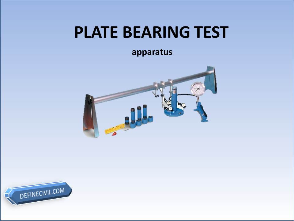
Plate Bearing Test Apparatus
A proving ring may be fitted with the Jack having 1 kg accuracy for measurement of the load
-
Bearing Plates
According to BS the circular bearing plates are recommended, the largest dia plate would be placed on the ground and other plates would be placed in concentric manner. However, Sizes of 350mm 450mm and 600mm are recommended. (on one of my projects the Contractor has assembled a rectangular bearing plate as well)
-
Four Dial gauges
These dial gauges would be used for checking the settlement of the bearing plate. These gauges must be checked for any zero error.
-
Reference beams.
The dial gauges are fixed on reference beams that are extended far from the loading zone, where no impact of settlement is expected.
Procedure of the Test
The general procedure of plate bearing test is very simple. It basically consists of loading a steel plate of known diameter and recording the settlements corresponding to each load increment. The test load is gradually increased till the plate starts to settle at a rapid rate.
The test is conducted by jacking a steel plate of known area against a resistance load, usually a heavy, tracked excavator. The size of plate is selected based on the scope of test and design load required, as well as the reaction weight (excavator) available.
By measuring and, subsequently, plotting the pressure (load/area) against deformation, the load bearing and settlement characteristics of the ground can be established.
All the steps for procedure would now be explained.
-
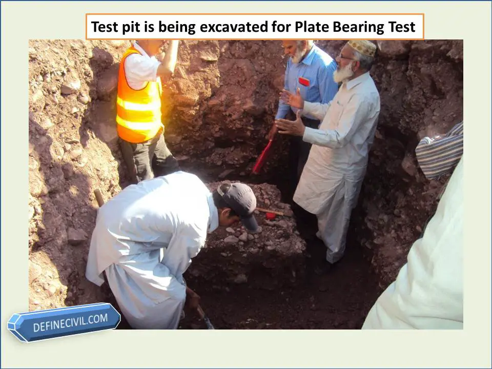
Preparing the test Site
The plate load test is normally carried out at the designed foundation level or the anticipated level of the footing i.e. it can either be on the surface or a shallow pit up to the desired depth can be excavated for carrying out the plate bearing test.
It is totally the decision of the Engineer at site that how much depth should be achieved keeping in view the site conditions. If the Engineer recommends the excavation of a test pit than the width of pit must be at least 4 to 5 times the diameter of the bearing plate.
- Selection of the size of Bearing Plate
Keeping in view the anticipated design load of the structure, the size of the bearing plate is decided by the Engineer at site. A size between 300 to 600 mm is fairly reasonable.
- Excavation and Preparation of Test Pit
Excavate to the test level as quickly as possible to minimize the effects of stress relief, particularly in cohesive fills. A mechanical excavator may be used provided that the excavator bucket does not have teeth and the last 100mm depth of excavation is carried out carefully by hand.
Carefully trim off and remove all loose material and any embedded fragments so that the area for the plate is generally level and as undisturbed as possible.
Protect the test area and the apparatus from moisture changes, sunlight and the effects of adverse weather as soon as the test level is exposed and throughout the test.
- Setting up the loading device and deflection recording devices
Set up the loading and deflection, measuring systems so that the load is applied to the plate without eccentricity and the deflection system is outside the zone of influence of the attachments.
During these operations a small seating load may be applied to the plate to enable adjustments to be made: this seating load shall be less than 5kN/m2.

The loading plate is placed on the ground and connected via a load cell to a reaction load. Due to the larger size of the plate used (compared with a CBR test) this test is more suitable for testing larger aggregate backfills, however, it requires a larger reaction load. Typically, a minimum 15tonne tracked excavator or other suitable plant is required for us to use as a reaction load.

- Application of Load and Note Deflection Readings
The load shall be applied in five increments. Settlement reading will be taken at 0.50 minute intervals for the first 2 minutes, and 1 minute intervals thereafter, until detectable movement of the plate has stopped, i.e. until the average settlement rate is less than 0.02mm per 5 minute interval.
At each increment the pressure shall be maintained as near as possible constant.
After the final test increment has been completed, the pressure in the hydraulic pump shall then be released and the settlement of the plate allowed to recover. When the recovery is essentially complete, the residual settlement value shall be recorded.

Apply the load to the plate in steps by means of hydraulic jack pushing against the counter weight until reaching the maximum test load. Unloading should also be done in the backward steps. Read and record the load of every step from proving ring.

Read settlement from the dial gauges. 3 to 4 dial gauges should be placed separately at 120° or 90° respectively.
Test Results
The total value of load on the plate divided by the area of the steel plate gives the value of the ultimate bearing capacity of soil. A factor of safety is applied to give the safe bearing capacity of soil.
Approximate equivalent CBR values can be derived from the Modulus of sub grade reaction by use of mathematical relationship.
Results from the test shall consist of raw data, load-settlement curve, yield pressure, recommended allowable pressure for foundation design, and modulus of subgrade reaction (K) for road design.

Plate Load Test Diagram
From the recording and results achieved from load plate test, a graph is drawn logarithmically between the loads applied in correspondence with the settlement. The load is indicated on the X-axis, and the settlement is indicated on the Y-axis.
The value of the ultimate load to be used on the plate can be found on the graph that is equal to a corresponding settlement equal to one-fifth of the plate Width.
The point at which the curve break, the load matching that breakpoint is determined to be the ultimate load required for the plate. From this ultimately determined load required for the plate, the ultimate value of bearing capacity and the best safe bearing soil capacity can be determined for the foundation.
[su_box title=”Must Read”]Do you want to know about the pile load test? dynamic one? go to this guide. Dynamic Pile Load Testing [/su_box]
If the bearing capacity found as a result of load bearing test is too high, Engineer should use judgment to limit allowable pressure to be more reasonable for each type of soil condition.
The prediction of settlement can also be done from the load-settlement curve from the test.
Advantages of the Test
- Gain understanding of foundation behavior which will enable the evaluation of foundation bearing capacity and settlement under loading condition.
- Quick and easy to perform.
Limitations
- Plate bearing test can give bearing capacity of subsoil up to the depth about twice of plate diameter only.
- The width of the test bearing plate should not be less than 30 cm. It is experimentally shown that the load settlement behavior of soil is qualitatively different from smaller widths.
- There is a scale effect due to size of testing plate is smaller than the actual footing.
- The settlement influence zone is much larger for the real foundation sizes than that for the test plate, which may lead to gross misinterpretation of expected settlement for proposed foundation.
- The foundation settlements in loose sands are usually much larger than what is predicted by plate bearing test.
- Plate bearing test is relatively short duration test and gives mostly the immediate settlements.
- In case of granular soils the immediate settlement is close to total settlements. However, due to considerable consolidation settlement in case of cohesive soils, the plate load test becomes irrelevant in such case.
Plate Bearing CBR Test
Where a CBR value is required for design purposes but the formation layer is either too coarse (>20mm aggregate) or a deeper loading profile is required, an equivalent CBR value may be obtained from plate bearing testing by using the modulus of sub grade reaction, via a mathematically derived formula.
Readings are taken for 5 increments of displacement (settlement) between 0 and 1.5mm and plotted against load. The approximate CBR equivalent value is then calculated from the load required to obtain 1.25mm displacement.
Download Plate Bearing Test Report (.XLXS)
You can download the Excel spread sheet of the test report for plate bearing test in .xlxs format for free by clicking the download now link below.
[su_document url=”https://definecivil.com/wp-content/uploads/2018/09/plate-bearing-test-report.xlsx” width=”440″ height=”440″]